E-mail
maryduan@sdprecisionpumps.com

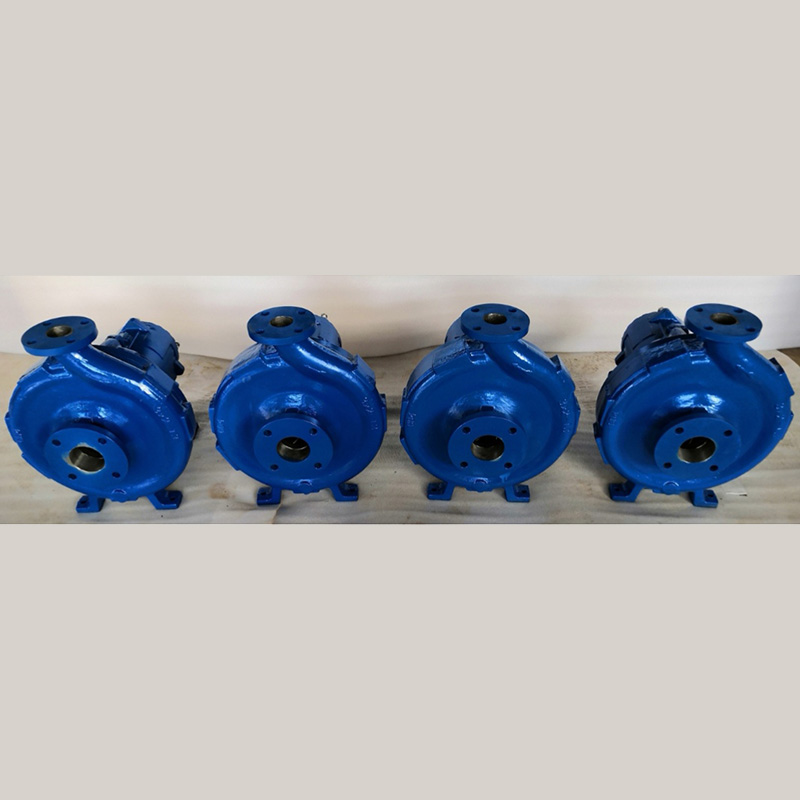
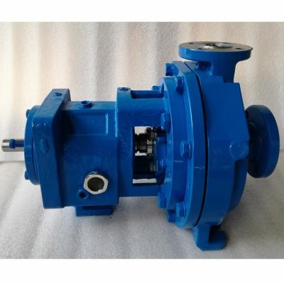
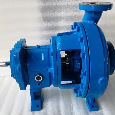
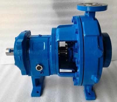
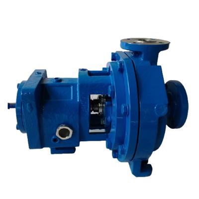
1.Our pumps could be 100% interchangeble with leading enterprise's Mark III series.
2.The wet ends material like Titanium, Nickel, Hastelloy C, A20, CD4M, 316SS, Cast Steel etc are all available.
TYPICAL SPECIFICATIONS
Design: Shall be of a horizontal, end suction, single stage, centerline discharge, “back pull-out” construction, meeting the design criteria of the ASME B73.1-2001 standard.
General: All wetted parts shall be permanently marked with the material of construction. Cast parts shall have a conditional lifetime casting guarantee. Stainless steel parts shall be cast to the ASME A744 standard.
Casing: Shall have a fully machined wet face and shall be capable of being foot or centerline mounted. Flange finishes shall conform to ASME/ANSI B16.5 and shall be available in DIN/PN16 or 40 (150 or 300 Class), flat or raised faces. Casing and rear cover plate shall have 3 mm (1/8 in) corrosion allowance.
Impeller: Shall be the reverse vane design, and shall be open on the back and shrouded on the front. The impeller clearance shall be set against the rear cover, not the casing, allowing all settings to be done in the maintenance shop, without the casing. The impeller shall maintain low seal chamber pressures, which shall be published on the pump performance curve, and shall be repeatable after maintenance. The impeller clearance shall be set externally. The impeller-to-shaft connection shall be a metal-tometal fit. A silicon O-ring encapsulated in PTFE shall be used to protect the impeller threads. Impeller shall be balanced to ISO 1940 Grade 6.3 criteria.
Shaft: Shall be of solid construction to maximize strength and rigidity. The shaft shall consist of a steel power end friction welded to an alloy wet end. Shaft deflection shall not exceed 0.05 mm (0.002 in). The shaft key slot shall be designed with a machined radius “sled runner” edge to provide maximum strength at the coupling. Critical surfaces shall be ground to 0.005 mm (±0.0002in), maximum roughness at the seal chamber shall be 0.40 µm (16 µin).
Rear Cover: Shall be suitable for accepting various seal designs from all majorseal manufacturers. Cylindrical bore standard, cylindrical bore oversize, and tapered options shall be available.Tapered options shall include eight evenly spaced, tapered and sloped flow modifying devices integrally cast into the seal chamber. The flow modifiers shall facilitate movement of solids,vapors, and heat away from the mechanical seal. The tapered seal chambers shall be designed to be self-flushing. For optimum performance the seal and gland shall be selected to locate the seal faces directly in the flush path. Integrally cast jackets shall
be available.
Bearings: Shall be large, heavy-duty, ball bearings. The inboard bearing shall be a single row, deep groove. The outboard shall be double row angular contact, deep groove. An optional duplex angular contact outboard bearing shall be available for high thrust load applications. Both bearings shall be located by a shoulder on the shaft. The inboard bearing shall float in the bearing housing,while the outboard bearing shall be locked in place in the bearing carrier. The bearings shall exceed B10 life of 17 500 hours and allow less than 0.025 mm (0.001 in) end play.
Bearing Housing: Shall be sealed to prevent contamination of the lubricant. The oil fill hole at the top of the housing shall be plugged. No vented constant level oiler shall be used. The housing shall be sealed with Inpro VBXX bearing isolators. A magnetic drain plug shall be used. A large easy to read one inch NPT sight glass shall be used. The impeller clearance shall be set by the micrometer adjustment method. This method shall cause the shaft and impeller to move axially. Indicators shall be cast into the bearing carrier which represent 0.102 mm (0.004 in) of axial impeller travel. This allows accurate impeller clearance to be established externally without the use of measurement devices.The bearing carrier threads shall be protected by two O-rings.


Submitted successfully
We will contact you as soon as possible